Thanks for the input guys, I appreciate it!
Here's some answers and clarifications:
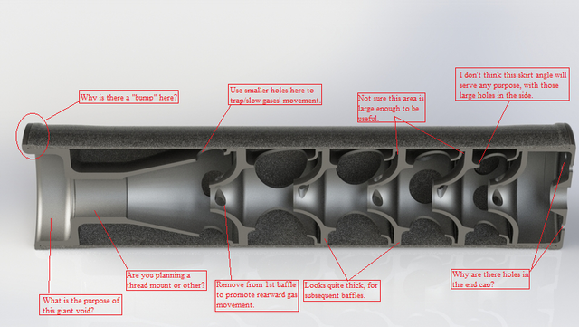
Why is there a "bump" here?
The ID of each end of the outer tube is threaded. The bump is a reinforcement so if I drop the tube during cleaning it is less likely to deform and make re-assembly impossible. There is also a less obvious increase in diameter over the threads to compensate for the loss of strength due to the material removed by the threads.
Use smaller holes here to trap/slow gas movement.
I've shrunk them. Still thinking about what a reasonable size/number is.
Not sure this area is large enough to be useful.
The intention with that geometry is to give the spacing skirt a very very small amount of flex so that baffle stack growth due to heat does not cause excessive stress to the outer tube. I maybe over thinking this problem and a simpler option would be fine.
I don't think this skirt angle will server any purpose with those large holes in the side.
My main intention with the skirt is to act as an spacer. The angle and holes are intended to make it lighter while also allowing the gasses to flow against the outer tube and cool off. I wanted to avoid a spacer that insulates and reduces the effective internal volume.
Why are there holes in the end cap?
I'm really not sure what I want the end cap to look like right now so I drew this quickly to have something to start with. The holes were to reduce back pressure.
Looks quite thick for subsequent baffles.
Agreed. Fixed.
Remove (turbulence ports) from 1st baffle to promote rearward gas movement.
Removed, although I'm still thinking about this. I might just make them really small. I'm currently stuck on the idea of using "jets" to disrupt and introduce turbulence in to the central gas flow, so I'm struggling with dropping them entirely.
Are you planning a thread mount or other?
That surface is 5/8-24 threads for a 30 cal barrel (300 blackout). I've just been too lazy to model threads into the surface.
What is the purpose of this void?
Weight and length savings. Pushing the rear tube threads back like that allows me to use the space over the barrel threads for my secondary expansion chamber while reducing the overall length by .44" and dropping 2oz of weight (compared to placing the rear tube threads over the barrel threads). Weight and length minimization are high on my priorities list. In this case If i move the rear tube threads to the traditional location over the barrel threads I gain ~2% more usable internal volume but increase my weight by 2oz (a 17% increase in weight). I'm not convinced this is a good trade off for MY priorities.
I'm still thinking about it, there may be a way to get the space without adding as much weight (without designing something that is un-machinable).
Here's a screen shot with a section of barrel "threaded" into it (outer tube removed):
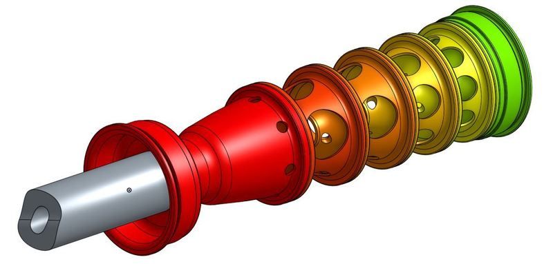
Sorry I don't have a cross section view as OnShape doesn't yet support section views of assemblies. If I was at work I'd send it over to solidworks, but I'm at home right now.
...your design seems to be all about turbulence and not enough about catching and slowing down the gas that is trying to get out.
I'm not sure these ideas are mutually exclusive. Turbulent flow will tend to have a harder time exiting the suppressor, effectively catching and slowing the gas. Part of my theory with this design is that any time I can get the flow to run into it's self, it is using up energy and slowing down. With this in mind, the radial turbulence ports are intended to both disrupt the central gas column and impart rotation to it. Each baffle then alternates the direction of rotation to try to get the flows to become as turbulent as possible. This might be a bunch of silly talk, but for now I want to stick to it while evaluating any ideas that could work better.
Overall, I know this design is not traditional. At this moment I'm not incline to just copy another design and run with it. The input so far has been awesome and I appreciate the thought in time people have put into their feedback.
Regards,
Phillip