Yes, it can be legal to make a silencer. For everything Form-1, from silencer designs that are easily made, to filing forms with the BATF, to 3D modeling. Remember, you must have an approved BATF Form-1 to make a silencer. All NFA laws apply.
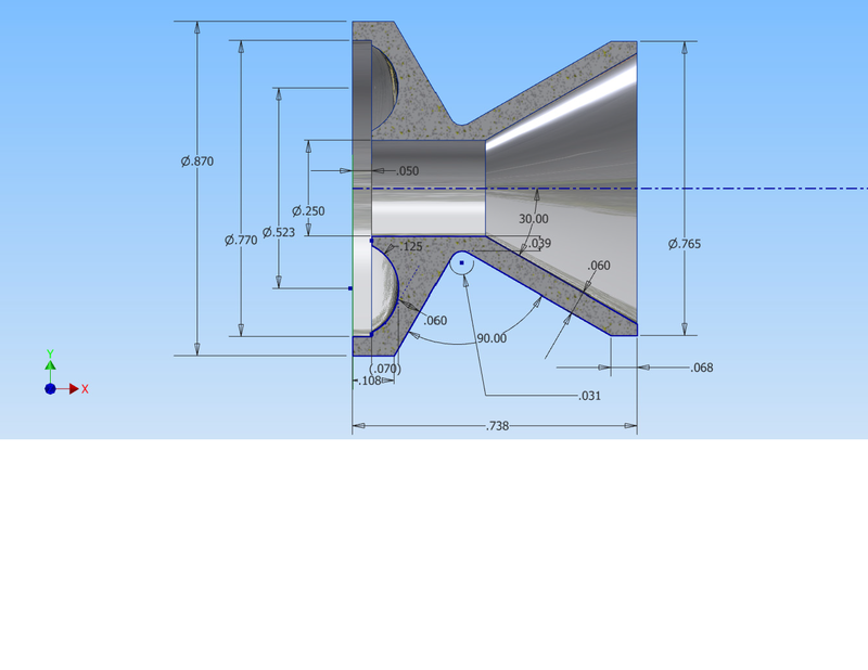
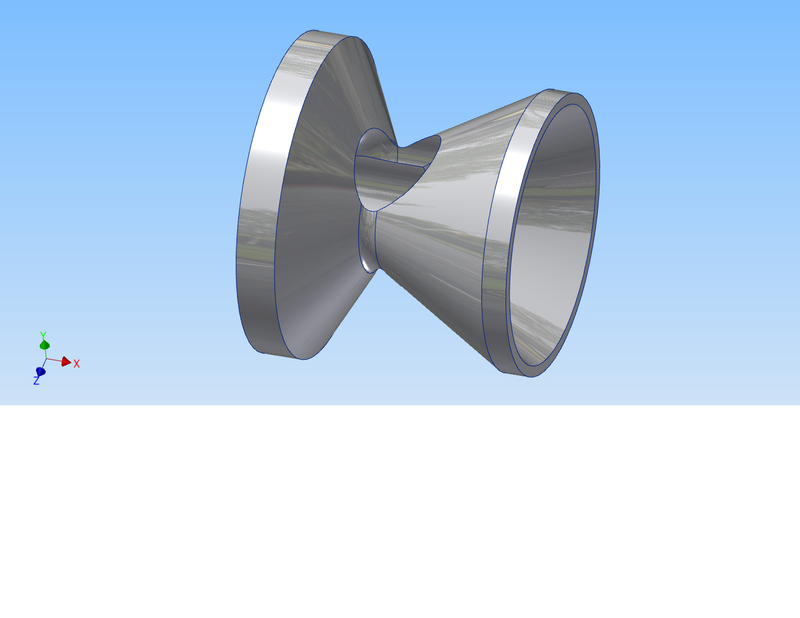
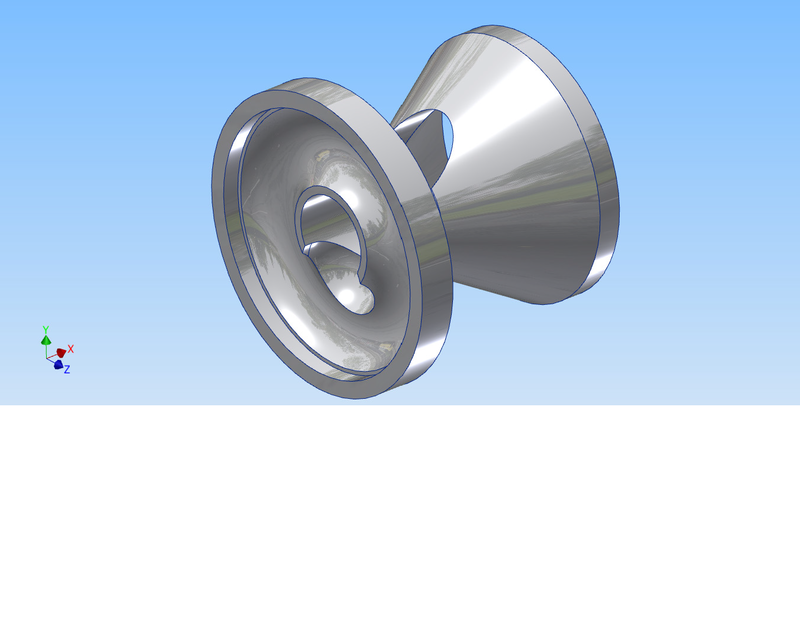
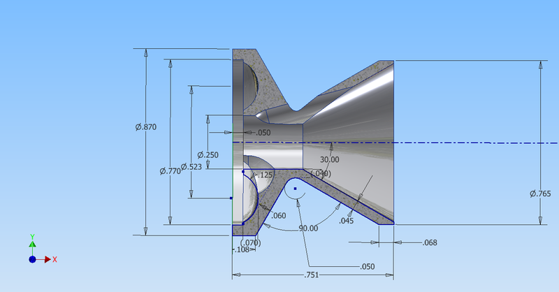
Is the scoop too deep? Is the mouse hole too big or too small? Is the front radius too deep or too shallow or does it need a different size radius? Are the center of the ball mills located correctly? All opinions are welcome.
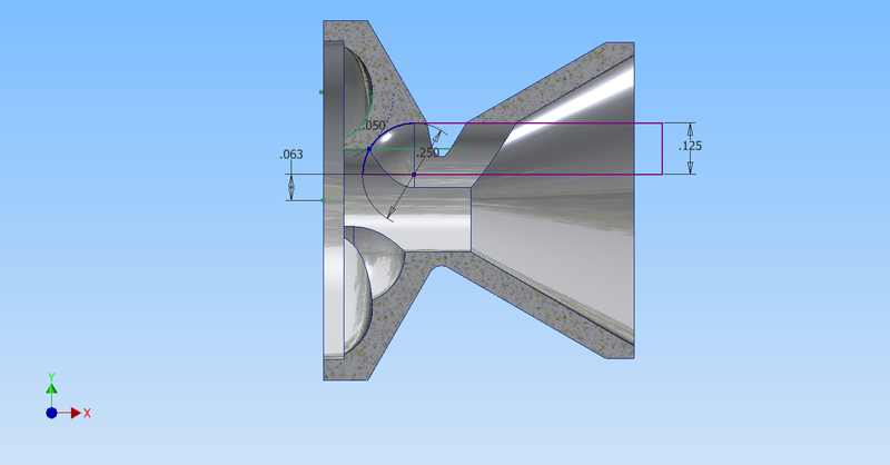
I'd suggest that it all looks good except for the vent hole placement in the waist. The resulting hole is so big that pressure will find an easy path back into the bore. You might consider moving the centre axis on your ball end mill to the outer edge of the bore hole, as the high pressure stream being jetted by the face vent across the bore should still have an easy time getting through a much smaller vent than what you're showing. Another refinement could be to tilt the baffle in the jig when milling that vent, such that instead of boring parallel to the main bore hole you're coming in at about a 15 degree angle. This will render a slightly more durable edge on the vent hole on the cone portion rather than a long knife edge such as this parallel milling approach leaves. Could be a factor in baffle longevity, depending on the intensity of the explosion with the ammunition being used.
I don't know if it matters at all but I cut the part that goes through the cone with a square end mill & not the same ball nose I do the little scoop in the face with. Same diameter, just a different tool profile.
What material are you using? Cone walls can be a little thinner if it's something stronger than 6061.
That small you might want not want to do the nested ends & just make the cone extend to the full diameter of the base and butt up against the next one.
--------------------------------------
"Sorry but you cannot use search at this time. Please try again in a few minutes"
"This board is currently disabled"
These things make me
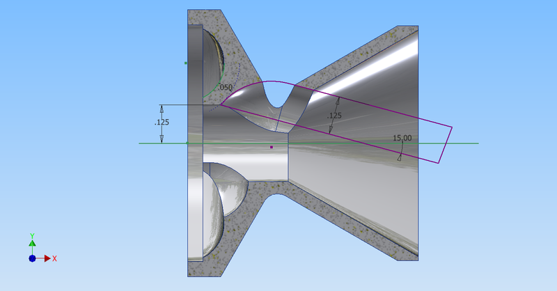
a_canadian wrote:I'd suggest that it all looks good except for the vent hole placement in the waist. The resulting hole is so big that pressure will find an easy path back into the bore. You might consider moving the centre axis on your ball end mill to the outer edge of the bore hole, as the high pressure stream being jetted by the face vent across the bore should still have an easy time getting through a much smaller vent than what you're showing.
Right now I have the center of the axis of the waist ball mill cut in line with the edge of the 0.250 center bore. Are you suggesting that I move the ball mill cut axis closer to the centerline of the thru bore? If so, any suggestions as to how much?
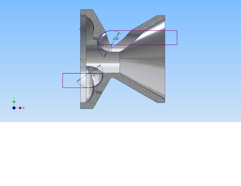
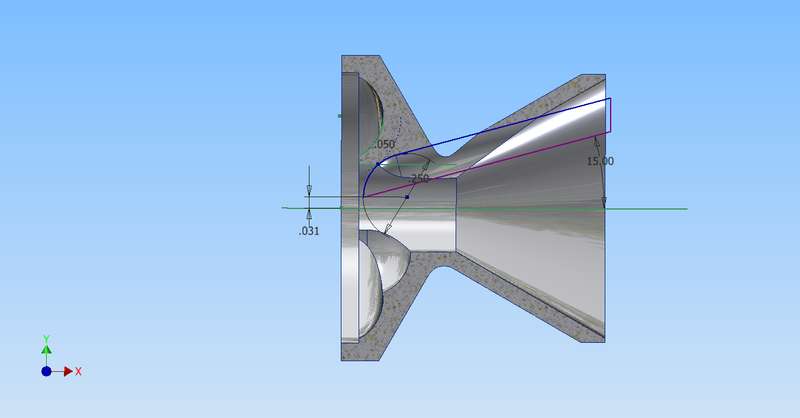
Like this?
Last edited by mcrump on Sat Nov 07, 2015 5:10 pm, edited 1 time in total.
CMV wrote:I don't know if it matters at all but I cut the part that goes through the cone with a square end mill & not the same ball nose I do the little scoop in the face with. Same diameter, just a different tool profile.
What material are you using? Cone walls can be a little thinner if it's something stronger than 6061.
That small you might want not want to do the nested ends & just make the cone extend to the full diameter of the base and butt up against the next one.
I am using 6061-T6 for all and will have 10 baffles. Does nesting make any difference? From what I've seen, I thought nested was the way to go. If not, less machining operations will save time.
Ah, sorry, looked at it too quickly and missed the axis position for the vent hole milling. Still, that initial vent looks too large. I like the modified position you're showing, or perhaps a compromise between them, just to get the vent big enough without being too big. Coming in at an angle from the cone end would allow a bigger hole with less aluminum being removed, if that's a possibility for you. A simple wedge under your clamping jig would get you the angle for a plunge closer to parallel with the opposite cone inner wall.
Nested should provide slightly easier dismantling for cleaning while also allowing you to sneak at least one extra baffle into a standard length suppressor tube. Win-win. Sure it's a bit fussier nesting them accurately but the bulk of your gunk build-up is going to be inside the cones and faces, with the stuff escaping the vent holes being relatively non-sticky, making it easier to slide the baffles out. With the cones touching the tube walls you'll get leakage of relatively intense gas, even some scorching at the seams between the first couple or few baffles, making it considerably more challenging to clean the inside of the tube.
7075 would be a much better choice. Easier to machine while also being much tougher so you can thin the walls on the cones perhaps 25%. You might also consider increasing the radius of that waist curve so as to thicken the waist slightly (which would also modify the axis position for the vent milling) as that seems to be a bit of a weak point. Look at the waist wall thickness compared to the structurally much stronger cone wall thickness. The cone is inherently strong, resisting pressure from the back efficiently and transmitting it to the next baffle down the line. A weak waist risks deformation after long use, crumpling the first baffle or two slightly and not symmetrically owing to the profound weakening caused by the vent hole in one side of the waist. Thickening the waist and thinning the cone walls would be a better use of the metal and provide a net slight increase in air volume.
a_canadian wrote:Ah, sorry, looked at it too quickly and missed the axis position for the vent hole milling. Still, that initial vent looks too large. I like the modified position you're showing, or perhaps a compromise between them, just to get the vent big enough without being too big. Coming in at an angle from the cone end would allow a bigger hole with less aluminum being removed, if that's a possibility for you. A simple wedge under your clamping jig would get you the angle for a plunge closer to parallel with the opposite cone inner wall.
Nested should provide slightly easier dismantling for cleaning while also allowing you to sneak at least one extra baffle into a standard length suppressor tube. Win-win. Sure it's a bit fussier nesting them accurately but the bulk of your gunk build-up is going to be inside the cones and faces, with the stuff escaping the vent holes being relatively non-sticky, making it easier to slide the baffles out. With the cones touching the tube walls you'll get leakage of relatively intense gas, even some scorching at the seams between the first couple or few baffles, making it considerably more challenging to clean the inside of the tube.
7075 would be a much better choice. Easier to machine while also being much tougher so you can thin the walls on the cones perhaps 25%. You might also consider increasing the radius of that waist curve so as to thicken the waist slightly (which would also modify the axis position for the vent milling) as that seems to be a bit of a weak point. Look at the waist wall thickness compared to the structurally much stronger cone wall thickness. The cone is inherently strong, resisting pressure from the back efficiently and transmitting it to the next baffle down the line. A weak waist risks deformation after long use, crumpling the first baffle or two slightly and not symmetrically owing to the profound weakening caused by the vent hole in one side of the waist. Thickening the waist and thinning the cone walls would be a better use of the metal and provide a net slight increase in air volume.
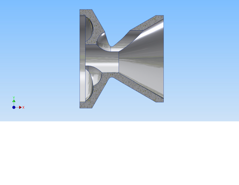
Like this? Cone walls are now .045 and waist is thicker.
Sorry, I must have been unclear in my explanation. I meant for the ball end mill to plunge closer to parallel to the OPPOSITE side of the cone from the vent hole. You're going almost parallel to the vent wall, leaving an even finer knife edge on the delicate aluminum at the lead edge of the vent hole. Not good. Might even cut you while cleaning, before it breaks down due to shooting and cleaning and becomes a much bigger vent hole.
The thinner walled cone makes more sense. Not sure I'm seeing much difference in waist thickness but I'll take your word for it.
a_canadian wrote:Sorry, I must have been unclear in my explanation. I meant for the ball end mill to plunge closer to parallel to the OPPOSITE side of the cone from the vent hole. You're going almost parallel to the vent wall, leaving an even finer knife edge on the delicate aluminum at the lead edge of the vent hole. Not good. Might even cut you while cleaning, before it breaks down due to shooting and cleaning and becomes a much bigger vent hole.
The thinner walled cone makes more sense. Not sure I'm seeing much difference in waist thickness but I'll take your word for it.
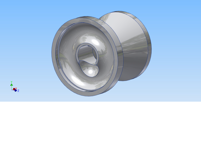
Bingo. What doesn't make it out the waist vent gets spread around inside the cone generating further destructive interference to the forward flow. A 'splash' effect for whatever's not making it out into the volume around the baffle. Should make for nice results.
a_canadian wrote:Ah, sorry, looked at it too quickly and missed the axis position for the vent hole milling. Still, that initial vent looks too large. I like the modified position you're showing, or perhaps a compromise between them, just to get the vent big enough without being too big. Coming in at an angle from the cone end would allow a bigger hole with less aluminum being removed, if that's a possibility for you. A simple wedge under your clamping jig would get you the angle for a plunge closer to parallel with the opposite cone inner wall.
Nested should provide slightly easier dismantling for cleaning while also allowing you to sneak at least one extra baffle into a standard length suppressor tube. Win-win. Sure it's a bit fussier nesting them accurately but the bulk of your gunk build-up is going to be inside the cones and faces, with the stuff escaping the vent holes being relatively non-sticky, making it easier to slide the baffles out. With the cones touching the tube walls you'll get leakage of relatively intense gas, even some scorching at the seams between the first couple or few baffles, making it considerably more challenging to clean the inside of the tube.
7075 would be a much better choice. Easier to machine while also being much tougher so you can thin the walls on the cones perhaps 25%. You might also consider increasing the radius of that waist curve so as to thicken the waist slightly (which would also modify the axis position for the vent milling) as that seems to be a bit of a weak point. Look at the waist wall thickness compared to the structurally much stronger cone wall thickness. The cone is inherently strong, resisting pressure from the back efficiently and transmitting it to the next baffle down the line. A weak waist risks deformation after long use, crumpling the first baffle or two slightly and not symmetrically owing to the profound weakening caused by the vent hole in one side of the waist. Thickening the waist and thinning the cone walls would be a better use of the metal and provide a net slight increase in air volume.
Like this? Cone walls are now .045 and waist is thicker.
Any chance you could post a link to the *.ipt file?
Your excellent presentation and layout of design elicits remembrances
of working with a K&E drafting kit, compasses, slide rule, ink stains, erasures,
holes in paper ... while the covered wagons rolled by.
a_canadian wrote:Ah, sorry, looked at it too quickly and missed the axis position for the vent hole milling. Still, that initial vent looks too large. I like the modified position you're showing, or perhaps a compromise between them, just to get the vent big enough without being too big. Coming in at an angle from the cone end would allow a bigger hole with less aluminum being removed, if that's a possibility for you. A simple wedge under your clamping jig would get you the angle for a plunge closer to parallel with the opposite cone inner wall.
Nested should provide slightly easier dismantling for cleaning while also allowing you to sneak at least one extra baffle into a standard length suppressor tube. Win-win. Sure it's a bit fussier nesting them accurately but the bulk of your gunk build-up is going to be inside the cones and faces, with the stuff escaping the vent holes being relatively non-sticky, making it easier to slide the baffles out. With the cones touching the tube walls you'll get leakage of relatively intense gas, even some scorching at the seams between the first couple or few baffles, making it considerably more challenging to clean the inside of the tube.
7075 would be a much better choice. Easier to machine while also being much tougher so you can thin the walls on the cones perhaps 25%. You might also consider increasing the radius of that waist curve so as to thicken the waist slightly (which would also modify the axis position for the vent milling) as that seems to be a bit of a weak point. Look at the waist wall thickness compared to the structurally much stronger cone wall thickness. The cone is inherently strong, resisting pressure from the back efficiently and transmitting it to the next baffle down the line. A weak waist risks deformation after long use, crumpling the first baffle or two slightly and not symmetrically owing to the profound weakening caused by the vent hole in one side of the waist. Thickening the waist and thinning the cone walls would be a better use of the metal and provide a net slight increase in air volume.
Like this? Cone walls are now .045 and waist is thicker.
Any chance you could post a link to the *.ipt file?
I can send you the .ipt file. It's in 2016 format. If you know Inventor you also know that you can't back save to an earlier release.