Page 1 of 2
G23 .40 Suppressor design progress
Posted: Mon Jul 16, 2012 11:38 am
by mx201er
I sent my papers in on June 4th, and hopefully will have the approved form in hand in the next few months for my .40 suppressor, which will go on my G23.
So far I have collected 1.35” x .065”wall Ti tubing, along with 1.25” Ti solid round stock, and I have a couple feet of 1.5” Stainless stock.
I am planning on doing all of the baffles out of titanium; the booster, booster sleeve, and rear cap out of stainless; and front cap out of aluminum probably. Here is the design I have come up with so far, I had a few questions before I can do much more..


So first off, the booster. I wanted to do a sleeve around the booster for several reasons: I didn’t know if a stainless booster would wear funny against a titanium tube, when it starts to wear the sleeve and booster will be easily replaceable, and when the booster is cycling the sleeve will hold the baffle stack tight so they don’t slide in the tube. The measurements that work best for me will allow an inch long spring, and allow the booster to cycle half an inch. Think that will work? The other question I had was that a booster with an OD of .690, after threading 9/16x24 for the barrel, would leave me with just over 1/16” of material from the widest part of the threads, is that enough or should I make my booster wall thicker?

Here is what I have for a baffle so far.

I will be adding a port to it but was having some trouble figuring that out, since I have never seen a k-baffle first hand. I looked at the “K-Baffles step-by-step” thread (
viewtopic.php?f=10&t=17116 ), which says that he did the port at 45 degrees and size ~.31 which was a little smaller than his bore. I tried drawing a 45 degree port with .3 diameter, but it seemed to drill through the whole cone on my baffle, as seen below. Its hard to see in pictures how the port is supposed to go, I was wondering if anybody would draw it in for me or link to a cross section picture somewhere? Should I use a smaller port and change the angle to around 60 degrees?

Also, would I benefit by making the flange on the front of the baffle thicker, so that I could do a deeper groove in the front? I’ll have to draw that when I get home from work to show you what I mean..
I would love to hear any ideas or thoughts, thanks guys!
I will document and share the whole build process once I am able to start the build

Re: G23 .40 Suppressor design progress
Posted: Tue Jul 17, 2012 12:43 pm
by Bendersquint
Ball end mill plunged straight down, not at an angle. All the successful K Baffles use this method.
The 45 degree +/- angle will not give you the performance you are wanting.
Re: G23 .40 Suppressor design progress
Posted: Tue Jul 17, 2012 5:08 pm
by mx201er
Bendersquint wrote:Ball end mill plunged straight down, not at an angle. All the successful K Baffles use this method.
The 45 degree +/- angle will not give you the performance you are wanting.
Thanks, its great to get info from somebody with experience. So straight down right up against the front of the k and all the way through one side (shown below), correct? Would ~.30 give good performance?

I was thinking about dropping a baffle in order to be able to increase the thickness on the front of each K by 1/16", which would allow a deeper groove in the front.. I was wondering if that would be better or worse?

Are there any other changes I can make to these baffles that you would recommend?
Thanks again Bendersquint
Re: G23 .40 Suppressor design progress
Posted: Tue Jul 17, 2012 5:46 pm
by Bendersquint
mx201er wrote:Bendersquint wrote:Ball end mill plunged straight down, not at an angle. All the successful K Baffles use this method.
The 45 degree +/- angle will not give you the performance you are wanting.
Thanks, its great to get info from somebody with experience. So straight down right up against the front of the k and all the way through one side (shown below), correct? Would ~.30 give good performance?
I was thinking about dropping a baffle in order to be able to increase the thickness on the front of each K by 1/16", which would allow a deeper groove in the front.. I was wondering if that would be better or worse?
Are there any other changes I can make to these baffles that you would recommend?
Thanks again Bendersquint
Give me a call and we can discuss it alot easier than trying to type it out.
Re: G23 .40 Suppressor design progress
Posted: Wed Jul 18, 2012 4:08 pm
by mx201er
Pm sent
Re: G23 .40 Suppressor design progress
Posted: Wed Jul 18, 2012 9:46 pm
by delta9mda
thanks bender for assisting. very lacking k baffles.
Re: G23 .40 Suppressor design progress
Posted: Wed Jul 18, 2012 10:00 pm
by jus2311
not sure I would use the ball end mill...not plunge cutting. you can use a "pot chuck" in your mill then plunge mill with a center cutting end mill with better results IMHO. Easier setup for op too.
Re: G23 .40 Suppressor design progress
Posted: Wed Jul 18, 2012 10:05 pm
by Bendersquint
jus2311 wrote:not sure I would use the ball end mill...not plunge cutting. you can use a "pot chuck" in your mill then plunge mill with a center cutting end mill with better results IMHO. Easier setup for op too.
There is a reason why almost all the manufacturers that make K baffles use a ball end mill. Just sayin.......
Re: G23 .40 Suppressor design progress
Posted: Thu Jul 19, 2012 12:07 pm
by jus2311
plunge milling? really? any 1st year machinist student knows better than that...just saying
Re: G23 .40 Suppressor design progress
Posted: Thu Jul 19, 2012 12:08 pm
by jus2311
maybe for the rear of the baffle for the "ramp" area for gas flow but def. not the side of the K or any other area similar in design to that
Re: G23 .40 Suppressor design progress
Posted: Thu Jul 19, 2012 12:58 pm
by Bendersquint
jus2311 wrote:maybe for the rear of the baffle for the "ramp" area for gas flow but def. not the side of the K or any other area similar in design to that
who said anything about plunge milling for the side of the k we were talking about the ports.
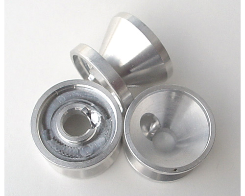
I was talking about the face divot and the underside divot/port opening.
Where the arrow is pointing on the face of my picture below, is a straight plunge with a ball end mill.

And the plunge from the ball end mill as seen in the lower right baffle below.
Re: G23 .40 Suppressor design progress
Posted: Thu Jul 19, 2012 2:18 pm
by jus2311
I stand corrected...my apologies....on pain meds for neck surgery. Will try and pay closer attention next time I am trying to keep my mind of the pain...
Re: G23 .40 Suppressor design progress
Posted: Thu Jul 19, 2012 2:20 pm
by jus2311
I would still not plunge mill from the face of the baffle with a ball nose end mill
Re: G23 .40 Suppressor design progress
Posted: Thu Jul 19, 2012 2:35 pm
by Bendersquint
jus2311 wrote:I would still not plunge mill from the face of the baffle with a ball nose end mill
Then how would you make the dimple on the face of the baffle?
Every single manufacturers K baffle dimple is done via a ball end mill.
Re: G23 .40 Suppressor design progress
Posted: Thu Jul 19, 2012 2:44 pm
by Enfield577
jus2311 I can only say that I followed these guys advice (including plunge milling the vents) regards K baffle design and have had excellent results.
I would strongly urge you to listen to what they say, I gurantee you will be happy with the results.
If you do a search on here under my name you can find the post I did with photos of the complete process to manufacture Ks
Best of luck
Re: G23 .40 Suppressor design progress
Posted: Thu Jul 19, 2012 3:49 pm
by rqlasl
I used a ball end mill and clamped my k's to the table of my drill press and plunge "drilled" them slowly. No problems or issues and they look pro!
Re: G23 .40 Suppressor design progress
Posted: Thu Jul 19, 2012 4:01 pm
by Bendersquint
i am still interested in finding out how he would make those without plunging.
Re: G23 .40 Suppressor design progress
Posted: Thu Jul 19, 2012 8:09 pm
by vz58
Plunge milling is absolutely acceptable if its the ONLY way to get a specific shape. Coolant and feed speed are key.
Re: G23 .40 Suppressor design progress
Posted: Thu Jul 19, 2012 8:29 pm
by Bendersquint
vz58 wrote:Plunge milling is absolutely acceptable if its the ONLY way to get a specific shape. Coolant and feed speed are key.
Yeah, I know, I have tried to will metal into dimpling but apparently the force is not strong enough in me so I plunge with a ball end mill.
Re: G23 .40 Suppressor design progress
Posted: Fri Jul 20, 2012 3:11 am
by Enfield577
I guess if you really had an issue with plunge milling (though can't see why) you could drop into the bore at full depth then index across to form the vent.
Just means you are taking quite a deep conventional cut on the cone end vent.
Re: G23 .40 Suppressor design progress
Posted: Fri Jul 20, 2012 4:55 am
by jus2311
other end mills can be used that would plunge mill with better performance...
Re: G23 .40 Suppressor design progress
Posted: Fri Jul 20, 2012 5:00 am
by jus2311
will try it with different end mills and see...I listen but will throw questions/comments in here and there regardless when I have some doubts on a particular op. or tooling used.
Re: G23 .40 Suppressor design progress
Posted: Fri Jul 20, 2012 5:16 am
by Enfield577
jus2311 wrote:will try it with different end mills and see...I listen but will throw questions/comments in here and there regardless when I have some doubts on a particular op. or tooling used.
No problems with you asking and making suggestions, hey that is how we all got on but I am not sure you got the idea of what you are trying to acheive.
The ball mill creates a scollop with a rounded base so that the gas is directed across the bore and is collected (scooped up) by the other port and sent to the out side of the cone. If for example you used a standard end mill or slot drill you would not really form a good scoop.
Anyway experiment (if you are allowed) and let us know how you get on (photos are good)
Oh and I love your drawings, excellent, I play with a very old version of AutoCAD LT, not in the same league.
Cheers
Re: G23 .40 Suppressor design progress
Posted: Fri Jul 20, 2012 2:29 pm
by jus2311
Understand the scoop being cut with the ball end...just a little confused about the area leading to the outside of the baffle to vent the gas....Delta cleared it up for me....just was looking at doing the op a different way and it didn't click in the brain housing group....ty
Re: G23 .40 Suppressor design progress
Posted: Fri Jul 20, 2012 7:46 pm
by mx201er
I know the baffle design is lacking, that is just my basic starting shape.. I have never seen a baffle in person, and was having a very hard time trying to understand the angles in the pictures I have seen. I think I finally understand how the port is supposed to go!
I have been looking at AAC Element baffles and have found some good pictures from various angles, and I am going to try to model my baffle to be similar to them.
Thanks for helping me understand, even as slow as I may be
